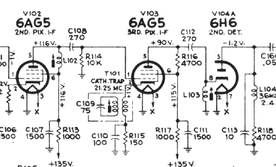
I set out to align the set using the "If the receiver is badly misaligned" method and I got a puzzling result. When I shunt the first two i-f amplifier grids and peak the third I get exactly the response that was expected. Adjusting the i-f transformer (L103) has direct effect on the voltage at the second detector load resistor (R118). I can turn the slug on the transformer and the voltage will raise to a point and then lower...exactly what it should be doing. If I adjust the signal output of the generator the voltage also rises and drops. So we're doing great and I move on to the second i-f stage. I remove the shunting capacitor from the grid of the second i-f tube and inject signal there. This gives me a completely different result though. Adjusting the transformer (L102) gives me no change in the voltage at the second detector except at the two ends of the the adjustment. When I adjust to almost the limit on the transformer the voltage jumps way up and the generator signal injection has zero effect on it. This is described in the service notes as i-f oscillation. It seems like there must be a problem between the grid of the second i-f amplifier tube and the grid of the third i-f amplifier tube. The only thing I found so far that was out of the ordinary was the plate voltage on the second i-f amplifier tube (V102) was high at 130V or so.