
|
|
|
#1
 12-18-2025, 01:13 PM
|
||||
|
||||
|
1936 RCA RR-359B Restoration
Alrighty. Let's get this started.
First some background. RCA did a number of field trials starting way back in 1931 to test the feasibility of commercial television service. These first sets were only 120 lines. Only 16 were made and at least one still exists. AM modulation for both audio and video with wide carrier spacing. No sideband suppression. Small experimental CRTs with green phosphor were used. Much more info in TELEVISION Collected Addresses and Papers on the Future of the New Art and Its Recent Technical Development Volume 1. Published by RCA INSTITUTES TECHNICAL PRESS.   Field tests continued throughout the 30s and not just receivers. All aspects from studios, cameras, control booths, transmitters, etc. Here's a slightly later 1933 model.   A few other experimental models were made over the next few years but none are known to exist. Which gets us to 1936 when they used all they had learned and started making the model RR-359A using a 9" green phosphor CRT with 343 scan lines for another round of field test. Come 1937 they upgraded most of the existing "A"s to "B's which included a 12" CRT and 441 lines. Seems they also produced a few more Bs. Much more info and photos in Television Vol II   Perhaps 100 were made in total. It's hard to find exact #s. I'm combining multiple published sources and bits picked up from other collectors. Complicated by RCA send a bunch over to the Soviet union to help get their TV industry going. What I can tell you for sure is that about 15 are known to exist around the world. Most in museums including two in the Smithsonian, one in Tokyo and several in Canada. Only 4-5 are in private collectors hands. I am now one of them and will be restoring it to the best of my ability and sharing all the details along the way. 
Last edited by bandersen; 12-18-2025 at 02:16 PM. 
|
|
#3
12-18-2025, 11:28 PM
|
||||
|
||||
|
Yes, mine has a pre-production 12AP4. There are three I know of in private collections that work. There is also one at the Early TV Museum in Ohio that was restored but has not been turned on in years.
I'll be visiting that museum soon to take photos and measurements to aid in my project.
|
|
#4
12-19-2025, 10:29 AM
|
||||
|
||||
|
OK, here's the good, the bad and the ugly.
This set is rough to put it mildly. If it wasn't, I would not have been able to afford it. It's my understanding last two examples on the market sold for $35,000 and $50,000! Here's a nice example of an "A" revision at the Early TV museum in Hilliard Ohio. Please click for more info. I typically visit this museum a couple times a year and will take many reference photos next time I go. 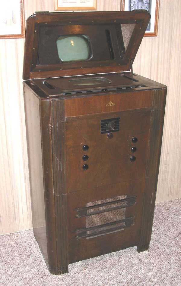 I purchased this set from another collector and can't take credit for finding it "in the wild". I was however provided some photos taken back then - around 5-6 years ago I think?    My "B" cabinet style is a bit different, but otherwise they are very similar. Right away we can see the front catalin knobs are missing and the tuner looks odd. The original tuner is gone! Someone drilled a hole in the cabinet and installed a later tuner which I do not have. It was removed by the previous owner who had intended to have the set restored. As the years went by, he changed his mind and put it up for sale. Overall, the cabinet is in poor condition and will require extension repairs and refinishing. Lots of veneer separation and loss. Much of the finish is completely gone. Maybe a job for Fred Taylor? The back is also missing which had an AC protection interlock. I'll either need to bypass it or fabricate a new back.    The leather surround on the beefy speaker has completely rotted away.  Now for the good. Both chassis are present and mostly intact. Also, the prototype 12AP4 CRT appears to be good - (have not tested it yet). The set had already been disassembled when I picked it up with the CRT safely packed away.      This is going to be quite an undertaking!  
|
|
#5
12-19-2025, 10:37 AM
|
||||
|
||||
|
"This is going to be quite an undertaking!" You have doggie there to help!
__________________
=^-^= Yasashii yoru ni hitori utau uta. Asu wa kimi to utaou. Yume no tsubasa ni notte. いとおしい人のために
|
| Audiokarma |
|
#6
12-20-2025, 11:58 AM
|
||||
|
||||
|
Thanks for the info. I have a wealth of info about the original tuner will get back to it in a bit. It's similar to what you describe but continuous tuning.
Next, let's take a look at the massive power supply. Easily 100 pounds. This is a sign of the times. Electrolytic caps were still a fairly new thing. Only four in the whole set and three are in parallel! Most of the filtering is done by massive filter chokes - even the high voltage.  This chassis is mostly original. Just one major repair. The original HV transformer has been replaced with one from a later TRK-12 model. Not exactly a perfect fit. They added a support bracket on one side. The other side is held down by some twisted wire. The original was held down by metal tabs fitted through slots in the chassis and bent over as was RCAs construction technique at that time. The original also had all the wires coming out the bottom while the HV leads comes out the side of this one. A bit ugly for sure, but I'm unlikely to find anything better anytime soon.  This also led to another issue. This set uses two HV rectifiers. One for focus and one for the main HV supply. That means we need two independent, insulated 2.5 VAC secondaries. The TRK-12 only uses one and a voltage divider for the focus voltage. Well, that means they had to add a dedicated filament transformer. That's the open frame transformer we see here surrounded by capacitors.  Speaking of caps. These are the four electrolytics I mentioned. Three 18uF connected in parallel for the main B+ filter and a 10uF for the push-pull 2A3s plate supply. The two at the top are originals while the others are replacements. It would be nice someday to replace them with period correct caps so they all match. The gnawed box to the left also contains caps. Two 10uF and a 50uF but they are not electrolytics. They are foil, paper and wax encased in tar. The are a couple more blocks like this on the upper chassis. That's good for me as they are easy to restuff. I will be using high quality polypropylene film caps to replace them all.  The HV supplies are brute force half-wave rectifiers on the 60Hz transformer secondaries. That's why they needed so much filtering. PI filters - two caps with a choke between them. I've been told the HV caps are oil filled and likely fine so I'll leave them alone for now. It uses and 878 and 879 rectifier tubes.  Not many parts down below. Mostly some bleeder resistors in the HV supply. Six 1M resistors in series right across the 6kV supply. 1kV on each is pushing them hard as 2W resistors are typically spec'd at 750v. I'll upgrade them when I build replica replacement dogbones. The phenolic board is warped and cracked. I may attempt to repair or replacement might be a better option.  Some rewiring will also be required. This set uses a mix of brittle failing rubber wire and cloth covered. I'll try to match them as best I can with new wire. 
|
|
#7
12-20-2025, 08:47 PM
|
||||
|
||||
|
Here's the PSU wiring diagram and chassis photos.
This and really all the incredible service info and photos I have are courtesy of Darryl Hock. I think it's fair to say without his fabulous cache of info and vast knowledge of these sets this project would be nearly impossible. There were never intended to be sold to the public and there's no Riders or Sams Photofact.   
|
|
#8
12-21-2025, 12:17 AM
|
||||
|
||||
|
That information should probably be scanned and uploaded to the ETFs website if it isn't already. Documentation like that should be preserved.
__________________
Tom C. Zenith: The quality stays in EVEN after the name falls off! What I want. --> http://www.videokarma.org/showpost.p...62&postcount=4
|
|
#9
12-21-2025, 12:57 PM
|
|||
|
|||
|
I wonder how similar your TV is to the RCA displayed on FDR's home in Hyde Park, NY? FRD spoke at the 1939 World's Fair in New York City and was given a TV. He gave it to his mother with whom he lived. She had an office in a nook between the main house and the library. He told her to put in the back corner because he didn't think television was going to amount to anything.
It was many years ago when I saw it and the guide said there were no plans to restore it. Last edited by Tom9589; 12-21-2025 at 08:56 PM.
|
|
#10
12-21-2025, 04:56 PM
|
||||
|
||||
|
If anyone could tackle this it would be you. Off you go!
__________________
Ham shack...AM side: Knight-Kit T-60, RME-45 Vintage SSB side: National 200 Modern SSB: Kenwood TS-180S MFJ tuner, 130' dipole
|
| Audiokarma |
|
#11
12-21-2025, 07:21 PM
|
||||
|
||||
|
FDR had a TRK-12. Conceptually similar, but it used newer tube types like the 1852
|
|
#12
12-21-2025, 09:49 PM
|
||||
|
||||
|
Sure, it will be like eating an elephant, but what a reward! I have zero doubt that it will work again. You might need to install a hoist to move that power supply chassis.
That CRT alone is a piece of art.
__________________
Bryan
|
|
#13
12-21-2025, 10:28 PM
|
||||
|
||||
|
LOL, yes that would be handy. I've already order up a heavy duty lazy Suzan turntable to put it on.
Now let's take a closer look at the upper chassis. Here's where things get really ugly. Here it sits just after I got it home.  As mentioned earlier, the tuner is gone. It was originally a continuous tuner covering around 40-90 MHz. Some sort of later tuner was hacked in where all we see all those blue labelled wires. Some run down through an empty tube socket. That's the mixer tube which I assume wasn't needed. Also, notice there is an empty tube socket on the left side. That's for the 1-V damper tube.  I popped a new one in and didn't think much of it until I noticed a more modern octal tube socket had been added at the bottom of the chassis.   I found a 117Z6 full wave rectifier tube in it with the filament connected directly to the AC line. Sure enough, it was wired to replace the 1-V damper.  While we're down here. Notice the mess? There are two candohm resistors down there with many taps. Likely some sections have gone bad and were bypassed with external power resistors. There wiring is also a mess and some caps have been added. How do I know? More on that in a bit.  Now, for the last major bit of ugliness. This was the vertical oscillator consisting of a 6A6 dual triode and blocking oscillator transformer. Instead, we have this mess. The original subassembly is completely gone and replaced with an 884 thyratron. More commonly seen as the timebase oscillator in early oscilloscopes. I suspect the original transformer went open and this substituted for it.  By the way notice the 001073 stamped on the chassis? Remember that.  I intend to restore the original circuit. Nice thing is the horizontal oscillator is nearly identical, and I can use it as a model.  The last bit of ugliness (so far) is all the tacked in caps. None of these are original or should be in these locations. Instead, there should be a box containing two this is missing. The rest should be in a box on the other side. The box is still there but bypassed. I'll be restuff / fabricating as needed and restoring the original wiring configuration. 
Last edited by bandersen; 12-21-2025 at 10:32 PM.
|
|
#14
12-22-2025, 10:56 AM
|
||||
|
||||
|
I mentioned the "001073" stamped on my chassis earlier. This is why I pointed it out.
RCA took fantastic, clear, detailed photos of the various parts of this set. Turns out the photos are of my chassis! That leaves zero doubt of what it originally looked like before the 12" factory upgrade to a "B". It's also neat to see the wooden support jig. I'll fabricate something similar for the workbench. Otherwise once I unmount that CRT funnel the chassis will tip over.  So much neater before all the repairs and modifications. Notice no caps on the left side and how clean it is along the bottom? This is what I am striving for.  This wiring guide will also be a fantastic guide as it not only shows all the wires but also the original colors. Now some of the changes are factory from the "B" upgrade. They added a 6H6 tube for example. So, I'll need to be cautious before I start clipping parts out. 
|
 |
|
|


 Linear Mode

