
|
|
|
#1
 05-04-2004, 01:44 AM
|
||||
|
||||
|
How NOT to Re-cap a Radio
Not too long ago I acquired a Westinghouse H-126 tube radio that displays some of the worst workmanship I've come across in quite some time. The radio had supposedly been "serviced", and now "plays extremely well." While the radio does work, after a fashion, it still has an intermittent pop that sounds suspiciously like one of those old wax/paper capacitors arcing out.
This is a beautiful radio from the outside, but after I dug into its innards, I was dismayed to see how poorly it had been serviced. Someone had obviously performed an ass/2 re-capping job, and the result would almost be humorous, if it weren't so depressing. Nevertheless, I resolved to keep my chin up, and remember Carlson's Consolation: Nothing is ever a complete failure; it can always serve as a bad example. So, with that sentiment in mind, I've attached some pictures that show How Not To Re-cap A Radio. I should mention first of all that, except for rare, museum-quality radios, I have no reservations at all about "spoiling" a vintage radio by installing modern components. These things were designed to play, and I think that we honor their designers by taking whatever steps are required to keep them playing. It's just that I think that we should also exercise care in seeing that the job is done in a professional and workmanlike manner. In that regard, I try to keep new all new components beneath the chassis. To me, this means leaving an original, above-the-chassis electrolytic mechanically intact, and taking care to position the individual capacitors that will replace it down below. Considering the rarity/expense of new multi-section electrolytics, and the relative small size of modern components, this is really the easiest and best way to go. Anyway, as you can see from the first picture, this guy chose to replace the original 3-section filter cap with an ill-fitting 2-section. Notice that its diameter is greater than the original, to the extent that it now crowds the output transformer, and leans drunkenly to one side. Also, he installed no clamp or other proper means to hold the new can in place. It's being held in position by the leads soldered to it's terminals. Great. The second picture shows the underside of the chassis where he located the third section of the filter cap. Notice the "creative" lead dressing, and solder joints hanging out in mid-air. There is a "flagpole" of bus wire sticking straight up from a solder lug, around which another lead is hooked like a cane, with the barest film of solder holding it in place. Notice also the "wax molded paper capacitor" lurking nearby. He replaced a total of eleven caps in this set, but left a total of three paper caps untouched. The third picture shows the other end of the chassis, where more creative lead-dressing and solder jointage are in evidence: globby, blob-like joints with random bits of wire poking out like porcupine quills, and enough singed components and insulation to make me wonder if he didn't use a branding iron instead of a soldering iron. I suppose a person could argue that it really doesn't matter as long as the radio "works". Who's ever going to look inside anyway? Well, I always do. It's probably just my imagination, but a radio that's been neatly and properly serviced somehow just sounds better, and I actually enjoy listening to it more than one that I know is hiding the evidence of someone's botched attempt at restoration. [/rant] Paula 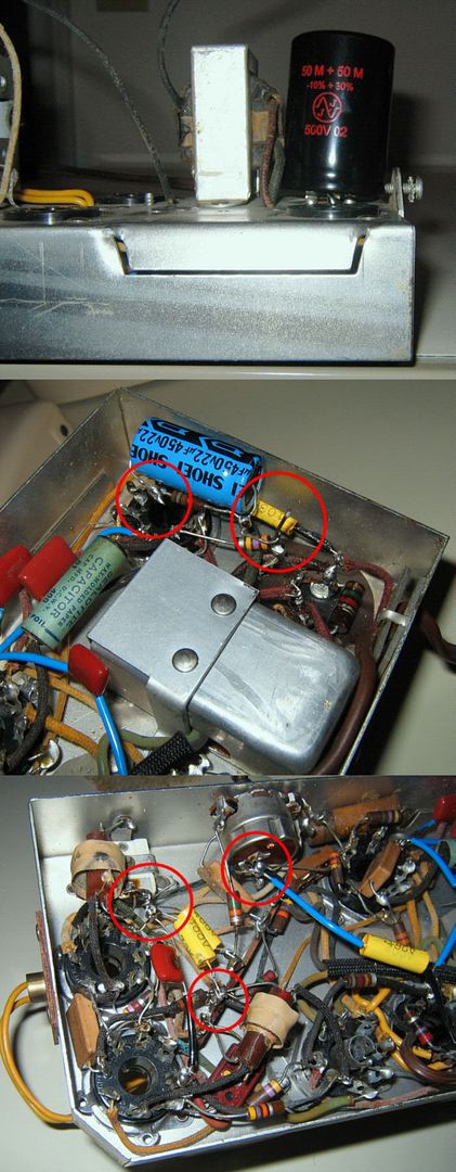
Last edited by Paula; 05-11-2006 at 04:52 PM. 
|
| Thread Tools | |
| Display Modes | |
|
|


 Threaded Mode