
|
|
|
#61
 02-23-2011, 10:28 PM
|
||||
|
||||
|
Hmm, maybe that fix worked after all. It's been playing continuously for hours with nary a blip. I turned off the set to feel the flyback and it's not even warm.
  Vertical linearity still needs improvement, but that's about all I've got left to fret over. Phil Nelson 
|
|
#62
02-24-2011, 12:24 AM
|
||||
|
||||
|
Picture looks super sharp from here.
 Kevin
|
|
#64
02-24-2011, 12:57 AM
|
||||
|
||||
|
I recommend Aervoe Industries Insulating Epoxy Coating for coating Flybacks and HV coils, perhaps prior to coating them with Wax or Silicone.
It has a rating of 2100 volts per Mil of thickness, probably well in excess of the voltage difference between individual turns of a Flyback. Also it's watery thin so it can flow deep into the windings and seal them. http://www.aervoe.com/paints_coating...y-Coating.html
|
|
#66
02-24-2011, 02:49 AM
|
||||
|
||||
|
No dashed lines, no ticking or sizzling. I wheeled it into my office and played it for six or seven hours, sitting two feet away from me. I haven't stuck a listening tube back into the HV cage, but when you turn the volume down all the way, it's as silent as any other tube TV.
I had actually given up on this flyback and just tried the repair out of curiosity. Good practice for a time when I might want to repair something that's not readily available. Since I've already ordered a new transformer, I may as well install that and keep this one as an emergency spare. An interesting experiment, anyhow. And now I won't be so nervous about putting a new flyback in this TV. If this funky old thing didn't go up in flames, I don't know why a new one would (knock on wood). If I ever do another one, I'll check out that Aervoe stuff. Phil Nelson
|
|
#67
02-24-2011, 08:59 AM
|
||||
|
||||
|
I guess I don't understand how the broken wire would have cooked the core?
 Was it the HV zapping outward from that brooken connection that melted all that insulation? Looking at the meltdown picture, I'd of guessed it heated from the inside out. Was it the HV zapping outward from that brooken connection that melted all that insulation? Looking at the meltdown picture, I'd of guessed it heated from the inside out.If it were mine, I'd leave the repaired old part in there and keep torturing it.  Kevin
|
|
#68
02-24-2011, 09:39 AM
|
|||
|
|||
|
Wow. Thought I had seen just about everything service-wise, but this is the very first 'Lazarus flyback'.
Regarding that DMM not reading cathode current, you probly need an analog meter there. Digital meters tend to balk or go nuts on anything with complex or high level waveforms.
|
|
#69
02-24-2011, 10:29 AM
|
|||
|
|||
|
if its working fine why not leave it be and keep the new as a spare?, dont kick over a rock just to see what crawls out..
I have a fly in an old maggie that works fine and make yours look mint by comparison.
|
|
#70
02-24-2011, 11:25 AM
|
||||
|
||||
|
Yah, who knows what really happened with that flyback. I know that I saw a big blue arc and a bunch of new melted wax, and I know that the TV works well now. The rest is all guesswork.
I dug out my little old dime-store analog meter and it pegged the needle in the 250ma scale, so I guess the current is higher than the 100-140ma given in the schematic (assuming that this 25-year old Radio Shack special is accurate). Not sure where to go with that, since the grid voltages on the HOT look normal, as noted earlier. http://antiqueradio.org/art/temp/Phi...MSchematic.jpg I'm a little peeved with Philco for using cheap sockets on the HOT and damper. Their terminals are above the chassis. 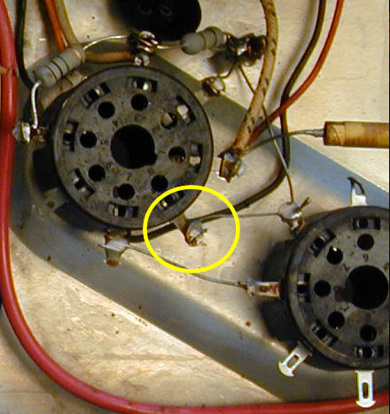 When I began unsoldering the cathode lead, the terminal instantly snapped off. Altoid tins are made of better material. The pin socket is like a bent strip of tinfoil with holes -- not very practical to repair. I have wonderful new sockets in the parts chest, but they're a normal style with terminals on the bottom. The original sockets are wedged into tabbed holes in the chassis, so replacing a socket with a standard type is not a plug-n-play job. Meanwhile, the TV plays fine with a cathode lead soldered directly to the HOT pin, so I'm tempted to pretend that I never saw those oddball sockets. Leaving the old fly in place is sounding better. Instead of looking for more trouble, I'll play the set for another long spell today and see how it holds up. Regards, Phil Nelson
|
| Audiokarma |
|
#71
02-24-2011, 11:45 AM
|
|||
|
|||
|
yikes 240ma
you may want to try that with something else, Thats more than I get on most of the color sets that operate at 25kv. A couple things I frequently do is add a cathode fuse (although that may or may not protect depending on how quickly it blows) and I add a B+ fuse right at the output from the diodes (if SS that is). The idea being it may save something in case of a runaway B+. I know its overkill but since parts are hard to come by, why not. the HOT cathode fuse makes for an easy check of currrent. Did you bypass the meter leads with a .1uf cap when reading the current? but all that aside, if its operating and not too warm, then I would just leave it alone.
|
|
#72
02-24-2011, 12:15 PM
|
||||
|
||||
|
There aren't many "something else" choices around here. I have a 50-year old Triplett multimeter, a flea market item that seemed to work when I briefly tried it with voltage and resistance. If I can scrounge a pair of probes that fit, maybe it's worth a try.
I didn't know you're supposed to bypass the meter leads with a .1 uf cap <blush>. Do you mean connect the cap between the cathode and ground, and then touch the meter leads to the cap leads? Phil Nelson
|
|
#73
02-24-2011, 12:16 PM
|
||||
|
||||
|
Quote:
 Or as you said, just pretend it's not ugly. And I'd just tag and leave the new flyback on the shelf, so you can break it out if the old one does die. Not borrow trouble. Oh, you could test your rat shack meter with a resistor and a source of DC (ohms law) to see what 120ma looks like on it. Though it's not DC on a cathode lead on a HOT. As mentioned above, use the 0.1uf bypass cap on that cathode, close to the tube. Back in the 70's I was in college (Syracuse University class of 78) and in a EE lab we built and played with el cheapo kit Radio Shack meters. One of the exercises was to show how the AC measurements were done by the meter, and that its circuit assumed sine waves only. Give it a square wave and the indication would be wrong. Found it recently, but the plastic became all crumbly, on the plastic knob shaft. Useless except as a souvenir of college days. With a sticker from a box of Raisin Bran at the time with the Sun logo saying that it belongs to WA2ISE. As for vertical linearity, you probably already replaced all the paper caps, so check the resistors. Dirt on the circuit board might cause some leakage.
__________________

Last edited by wa2ise; 02-24-2011 at 12:25 PM.
|
|
#74
02-24-2011, 06:54 PM
|
||||
|
||||
|
Fixing the socket terminal was a good idea. I got a wire through the side of the socket, wrapped it around the little holed piece on the inside and the old stub on the outside, and soldered. Left a pigtail until I'm done messing around in that area. It won't survive caveman yanking, but the original terminal wasn't that sturdy, either
  With a .1 uf cap in place, I measured 118ma cathode current with the Triplett meter. That's the middle of the 100ma-140ma range given in the schematic. I'm going to quit stressing over this, since the voltages on the HOT and general performance are also normal. The vertical (drive?) line definitely becomes more visible if you turn the fine tuner CW to the point where focus becomes too sharp and you start to see ghosting contrast lines on the sides of objects. If you back off on the finer tuner, it basically goes away. I'm crossing that off the problem list, too. Re the linearity, I previously replaced three resistors on the sweep board (R65, R69, R70) and that improved it somewhat. I just replaced three more (R66, R67, R68) and it's about the same. Please don't tell me it's the vertical integrator K1; I have built replacement integrators before, but they're kind of a pain. Thanks, Phil Nelson
|
|
#75
02-24-2011, 11:56 PM
|
||||
|
||||
|
Looks good. I'd probably just solder the other end of that pigtail to the terminal of the other tube socket (gently!), maybe creating a loop with the old wire to hold the pigtail to the terminal when you solder.
As far as vertical linearity goes, did you replace the vert out tube's cathode bypass cap? I had one go bad, and IIRC with it bad I couldn't get reasonable linearity.
__________________
|
| Audiokarma |
 |
|
|


 Linear Mode

