
|
|
|
#1
 11-24-2015, 01:46 PM
|
||||
|
||||
|
Sony DVK-2400 and DVC-2400 set
This is the same kit that belonged to Sean730. I got it on the promise to use it for something and I dang well will.
 Now that it's up North I've had a better chance to look it over. The appropriate service manuals and instruction manuals came along with it but both the camera and the VTR are extremely rough. Lots of dents. Lots of scratches. At least the external power supply is the proper one so yes Sean, it will work fine.  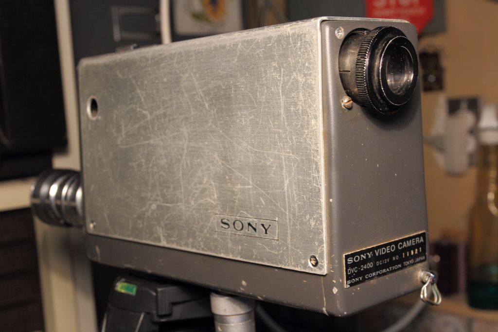 The viewfinder eye cup was nowhere to be found and the viewfinder was rattling about. It had also stopped displaying a distorted raster which was not promising. Opening it up however I discovered the plastic friction ring for the viewfinder had broken into three pieces at some point and a third of it along with a screw had simply vanished. The fact that one of the screws was also not original meant someone had been in here before to investigate the same problem. The dead CRT turned out to be the tube had shifted forwards enough that the socket popped off. This thing must of been REALLY tossed about in shipping as it must of taken a decent amount of force to shift the tube at all while clamped but I gotta hand it to Sean, his packing job was A+ and nothing was damaged. Pushing it back and plugging it back in once again gave me the distorted raster. Something's wrong but before I can play with the camera to find out what exactly the VTR needs to be inspected given how it generates the sync signals for the camera to work at all. The lens was also not the original. At some point they had changed it for a 13mm Elgeet. By the time I got it the grease in it had gummed to the point neither the focus or the aperture control would move. While a teardown and cleaning fixed that I couldn't seem to get the focus ring to mesh with anything to make the lens actually focus so either I've forgotten a reassembly step or further problems are afoot. Well at least it uses a C-mount thread so I can use one of my other lenses. 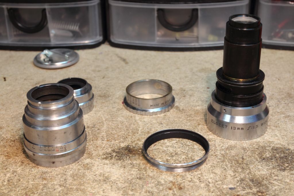  I needed to get the VTR working before I could go any further. The manual stated that the head should spin up when put in standby but it did not. The manual also states that the initial spinup applies a heavier load using another circuit so either that circuit had failed or it wasn't being powered. I briefly scanned the service manual and began following the procedures to test and adjust the voltage regulator. The first issue was that while the +12 was fine the +9 was not. The regulation circuit consists of a 2SD28 which tested fine and two 2SC401's. One tested fine but the other did not. 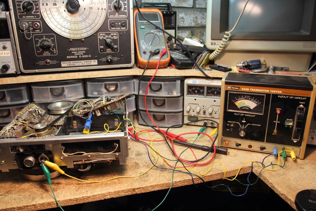  There are a number of known substitutes but they are all equally as obscure but at least not too expensive on ebay. Couldn't find anything to verify if a 2N3904 would work instead. Need opinions here. While there are two belts in this thing I'm surprised at their condition. They aren't immediately unusable or not stretching back into place but only time will tell if they are still good. There's also two plastic screws for the 2SD28 which have broken and will need to be replaced. Stay tuned for more.... 
|
|
#3
12-11-2015, 10:53 AM
|
||||
|
||||
|
Cautious experimenting yielded that in the end a regular 2N3904 would work as a substitute. After a bit of adjustment the 9v now present.
Going back to our more priority issue, we still do not have drum rotation. That I can tell from the documentation it should spin up the moment you put the VTR in standby with an intermediate circuit to handle the initial starting load. Instead it just sits there. 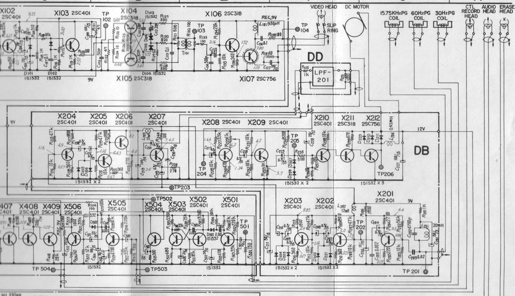 The diagrams say that the motor connects at points 1 and 4 on the DB board. Those two points when in standby read 11.5v so a voltage is present but weather or not it's what we're looking for might not be the bigger problem. Reading for a resistance across the leads from the motor and presumably its winding are infinite.  Either the lead to the motor has gone bad, the motor doesn't have a type of winding I'm expecting....or the winding has opened. Unless my observations are wrong that's the end of the line. Getting at the motor isn't at all easy and requires removal of the precisely aligned video head and surrounding mechanism which I do not have the tools to confidently realign. Edited: The exploded view of the drum shows that there's an intermediate contact I forgot about. There's brushes or something similar inside. That's another potential fault point but again, it's located underneath the video head and cannot be removed form the underside. Edited: THREE BEERS LATER:  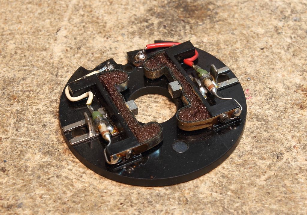 Well there's the problem. The motor brushes are pressed against the commutator with a thin metal bracket and foam. No surprise but after 50 years said foam has lost its ability to spring back, resulting in pretty much no contact. I'm not entirely sure how to proceed from here. Any ideas? Last edited by MIPS; 12-11-2015 at 01:23 PM.
|
|
#4
12-11-2015, 12:28 PM
|
||||
|
||||
|
Sony calls out a 2SC403/A/B/C for the 2SC401, per the Sony 1981 (July) Semiconductor Replacement Handbook Supplement. 2SC403A's come up in a Google search, if you want originality...
Cheers,
__________________
Brian USN RET 22YRS (Avionics/Cal) CET-Consumer Repair and Avionics ('88) "Capacitor Cosmetologist since '79" When fuses go to work, they quit!
|
|
#6
12-13-2015, 01:32 PM
|
||||
|
||||
|
Progress has been...promising so far.
I used a brand new box cutter blade and tried carving up some pink antistatic foam. I keep this stuff around for storing and transporting the very large boards my Silicon Graphics machines use and I find chemically it's quite stable. A lot of experimentation found that after cleaning out the old foam and slipping in the new foam with tweezers I could reduce the commutator gap by about 1-1.5mm. Not a lot but given how close the brushes were previously when the foam wasn't expanding this should be enough to achieve a proper contact. Initial tests on the bench at least seem so show that there is a resistance from one brush lead to the other.  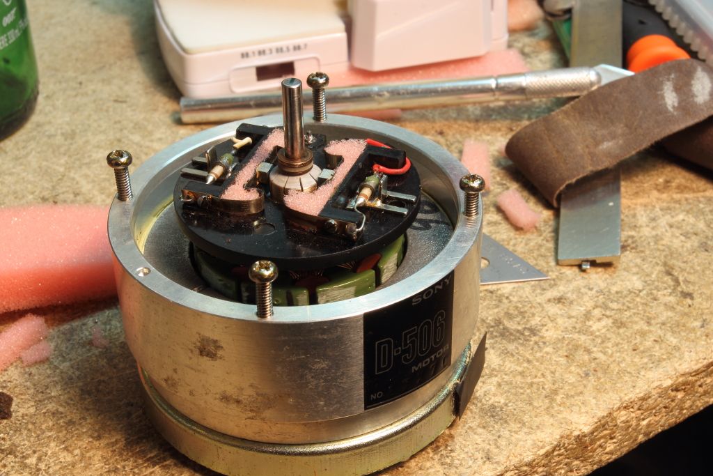 I really wish I knew what the original foam pieces looked like or how rigid they were. Edited: Further searching has found this problem is NOT exclusive just to the 2400. It happens as well on at least one other model of tape machine, the AV-3400 as well. (read 3/4 of the way down) Last edited by MIPS; 12-13-2015 at 02:43 PM.
|
|
#7
12-15-2015, 01:53 PM
|
||||
|
||||
|
Success.
The reassembly went well enough. There were slight issues though. First was that reassembling the motor was a pain. You must somehow hold the brushes back so the rotor can be slipped in, then the rotor shaft must be clamped or somehow retained so when the magnetic other half of the motor is put in place the rotor doesn't pull itself out of its seat and pop off the brushes. This is made a little more harder by one wire harness that kept getting pinched between the two halves but once they were assembled a continuity check verified that we were good and it was screwed together.  The second issue is purely my mistake. While I was marking where on the shaft the various components were while they were removed, I didn't think about the vertical head positioning. It's kinda critical. Too high or too low and it would contact the drum. I also assume the recorded video would be offset form where it also would be. I totally should of checked the height with the calipers. The proper height is not listed in the service manual. After some playing I found that 7mm seemed to work. The head was not centered (and can't be because it sits underneath the mechanism and is mounted by an epoxy blob) but the assembly was evenly spaced between the top and bottom halves of the drum.   Reassembly of the top half was no problem as none of the precision adjustments had been touched. Simply bolt it back in, reset the video head brushes and you were done. 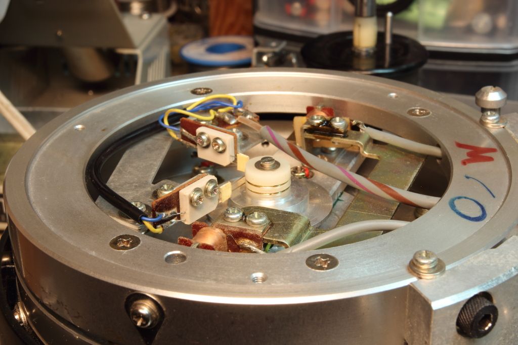 Finally the motor was connected to the bench supply and slowly brought up to a safe 10v while checking for excessive noise, vibration or other bad things. None were noted so the motor was reconnected to the machine, the bench supply set to 12.00v and the motor speed checked and adjusted. 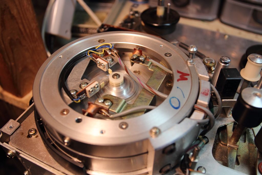 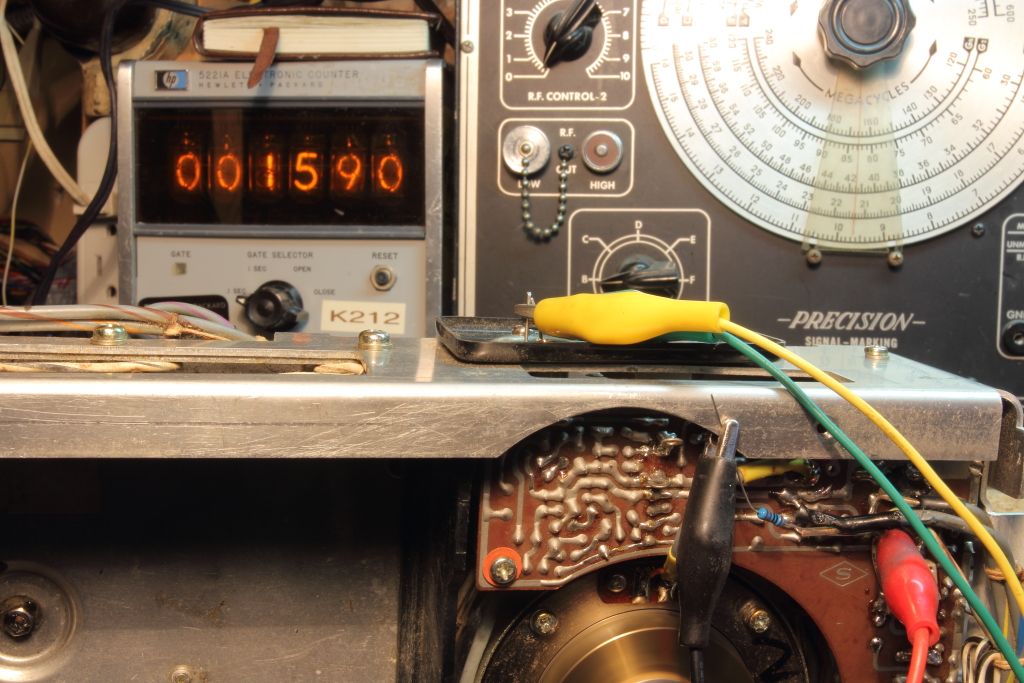 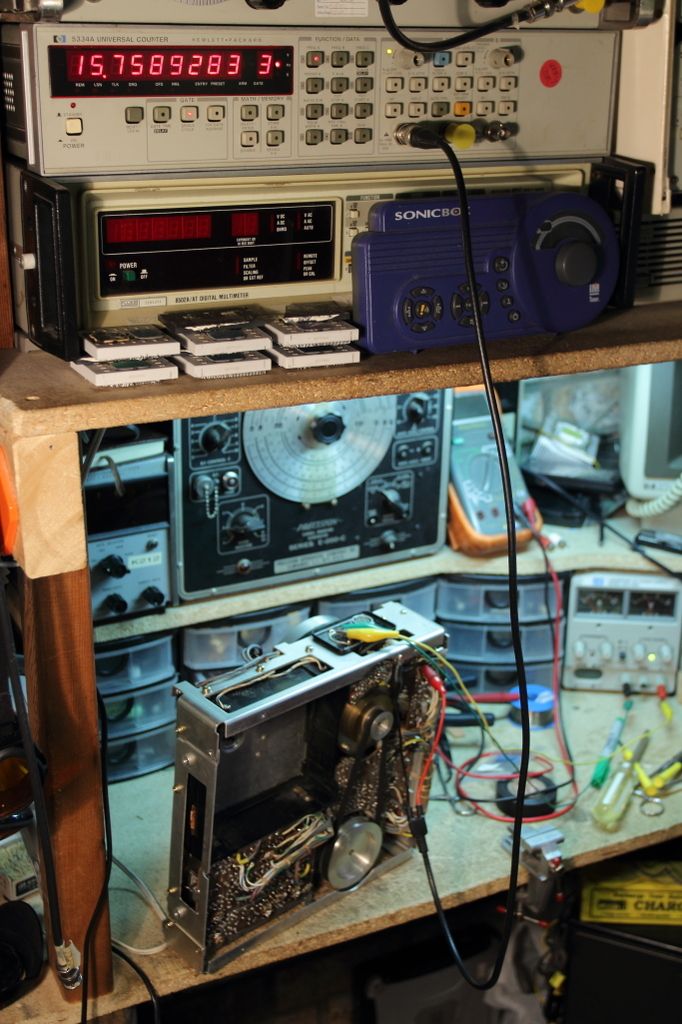 The 5221a was rounding to the nearest 10 so I had to switch over to the 5334A to set the speed. The camera now whines the high voltage at a different frequency, so presumably it now has a sync signal. Unfortunately there's still no picture. Once I'm done verifying the signal form the tape machine is good I'll move onto the camera. Last edited by MIPS; 12-15-2015 at 02:01 PM.
|
 |
|
|


 Linear Mode

